
NVIDIA Jetson Orin NX
Depth, perception and the safety wrapper run on board. Your robot gets results, not raw pixels.
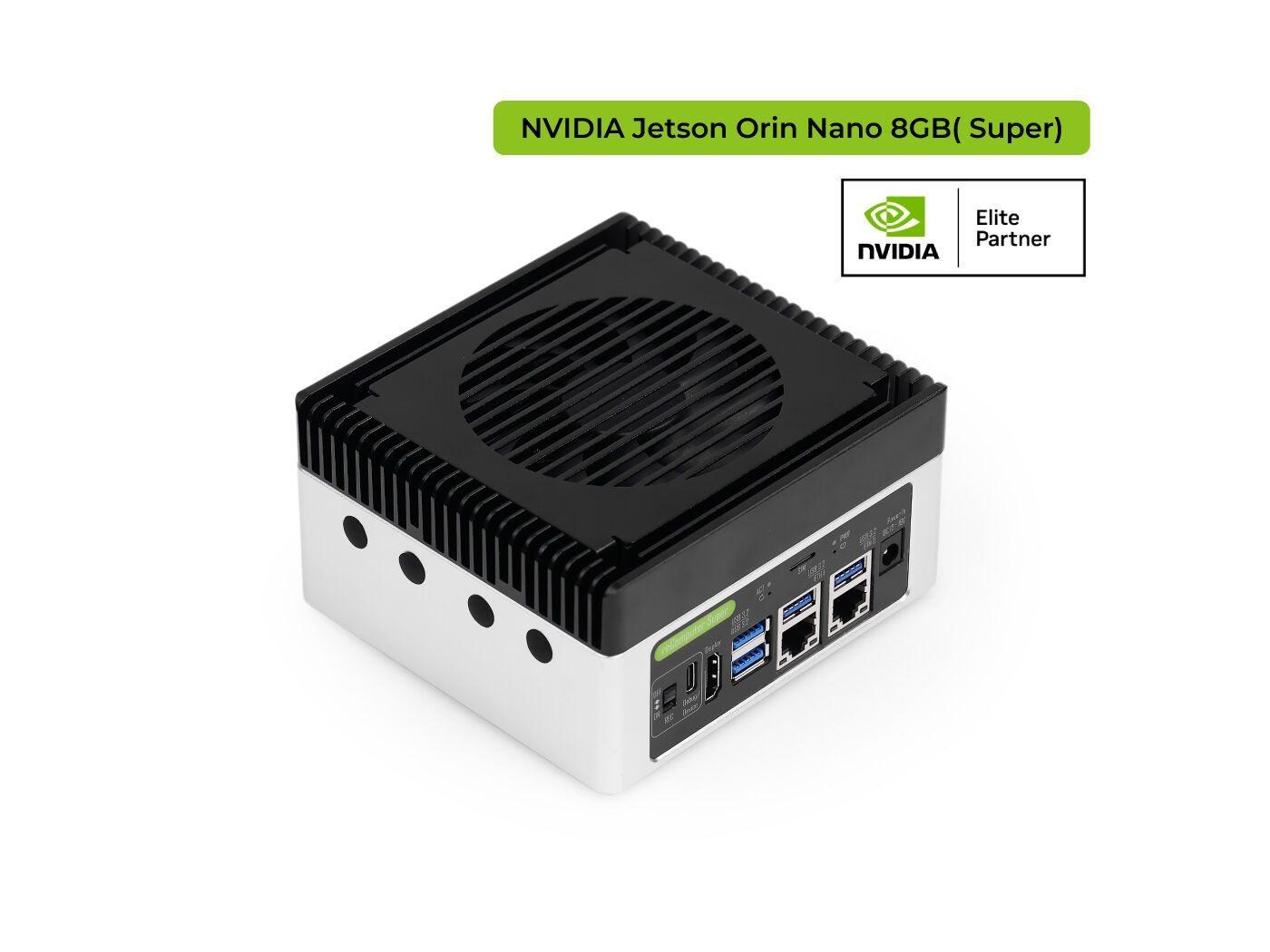
- Output
- Ethernet · SDK · ROS 2
- Safety
- SIL 2 / PL d (target)
3D stereo safety sensor for AMRs and AGVs with automotive series cameras. Protective field and perception in one device.
 Visualization
Engineering Kit
The same qualified building blocks, combined per vehicle: surround safety for AMRs, front and rear fields for pallet AGVs, wide 3D perception for humanoids, long range for outdoor machines.
Depth, perception and the safety wrapper run on board. Your robot gets results, not raw pixels.
Wide 3D stereo depth right around the vehicle: raised forks, overhanging loads, people bending over.
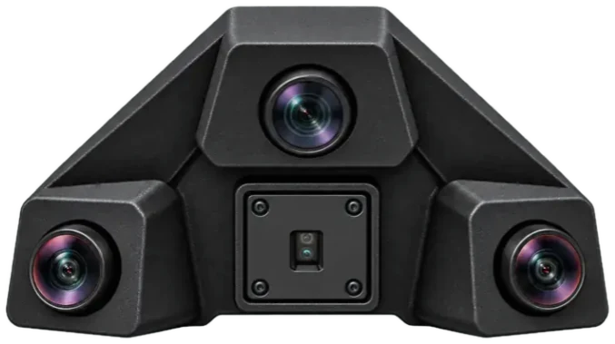
A 120° long-range eye for object and boundary detection, far beyond the stop distance.
A metric cross-check of the stereo depth for applications that want a second physical principle.
How it works
Three perception algorithms run in parallel and are fused into one 3D free-space map. The safety function decides on that map, while object classes and tracks come on top for docking, navigation without additional hardware needs.
Sees the aisle ahead and the area right around the vehicle, in 3D, not just in a single scan plane.
Your robot knows where it may drive, what is in its way (a person, a forklift or a rack) and how far away it is.
Low- and mid-level fusion of all three algorithms. Every result is checked against the others before it counts.
One reliable picture of the shop floor for safety, path planning and docking.
The safety function, designed for SIL 2 / PL d, decides on the free space map and triggers the safe state.
With object classes and tracks, navigation in mixed traffic and smarter fleet behavior with reduced downtime is enabled.
FuSa AI Agents
TriRide's agentic FuSa AI system verifies hardware and software functional safety requirements from building blocks that are qualified once, their integration, and automatically generates standards-compliant work products.
done · package ready for engineer review and sign-off
separate from every author
Requirements first, then system, hardware and software analysis, then the quantitative metrics, the safety mechanisms and finally verification. Each phase is gated by the orchestrator.
Applications
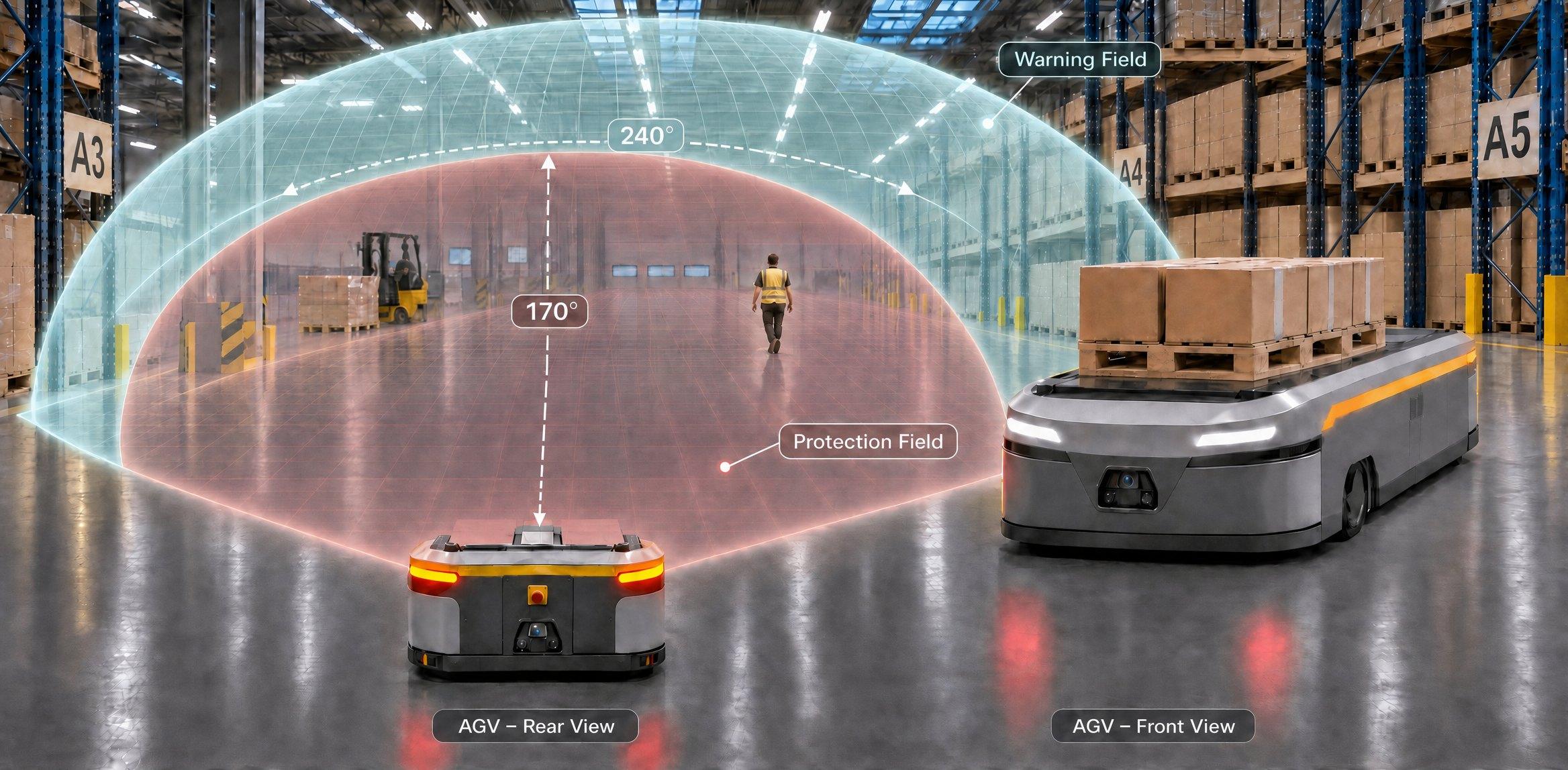
Top view, schematic. Blue is the 3D field of view, red the protective field that triggers the safe state, amber the warning field that slows the vehicle down.
Goods-to-person and transport robots in shared aisles. One module covers 240° in 3D around the front and sides, so people stepping out of a rack row are seen before they are in the path. The warning field adapts to speed, so the robot slows down instead of stopping, and keeps moving when the aisle is clear.
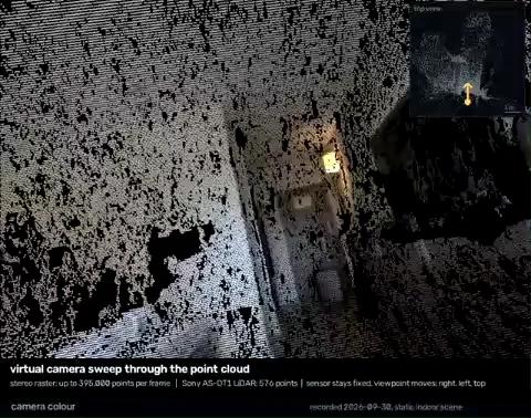
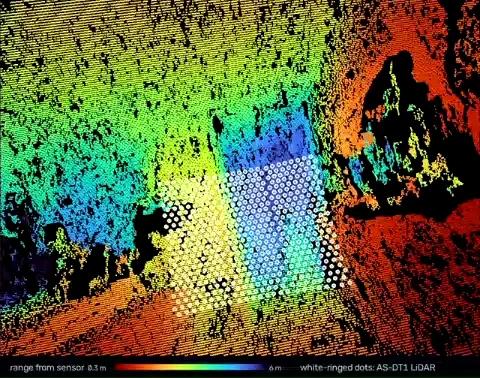
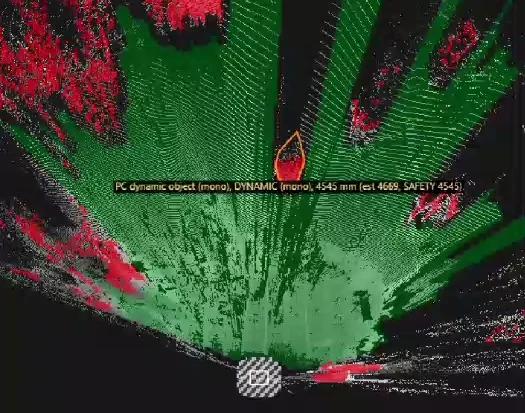
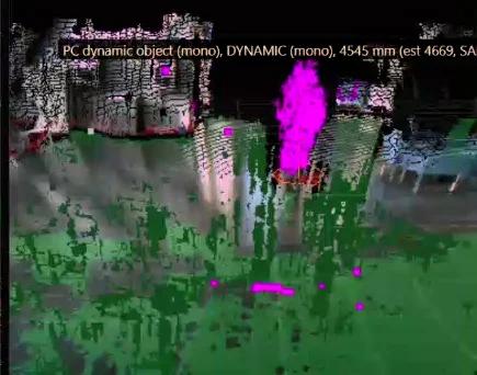
Data Footage
One device for perception and safety on mobile machines, dense 3D stereo depth, free space and 2D perception. The camera calibrates itself during runtime.
What you get
Evaluation kit
Test TriRide on your own vehicle, in your own hall.
Request a kit →Pilot project · together
We work out the safety solution for your vehicle with you, from mounting to the documents your assessor needs.
Roll out · scale
Qualified blocks are reused for every new variant. Instead of starting from scratch, you only qualify what changed.
Let's talk about your robot →Brochure
| Technology | Passive 3D stereo, multi-baseline, with LiDAR |
|---|---|
| Protective field range | 4.0 m (body, 200 mm) · 3.0 m (leg, 70 mm) · 2.0 m (arm, 40 mm) |
| Warning field range | 10 m |
| Field of view | 175° × 165° (3D Stereo) / 240° × 165° (2D Mono) |
| Response time | ≤ 100 ms |
| Simultaneously monitored fields | 3 per field set (1 protective, 2 warning); ≥ 32 field sets |
| Safety integrity level | SIL 2 (IEC 61508) |
|---|---|
| Category | Category 3 (ISO 13849-1) |
| Performance level | PL d (ISO 13849-1) |
| PFHD | < 1 × 10⁻⁷ /h |
| Architecture | 2oo3D over 3 stereo pairs, 1oo2D with LiDAR (HFT 1) |
| Protective field switching | ✓ (by vehicle speed, steering angle) |
|---|---|
| Self-monitoring of camera alignment | ✓ |
| Deterministic (Safety) + AI (Comfort) | ✓ |
| Measured data output | ✓ Point Cloud+, BEV, Moving Objects with TTC |
| Image sensors | 2 × 3 MP fisheye 200°, 1 × 8 MP 120°; automotive series |
|---|---|
| Depth range | 0.2 m … 15 m |
| Depth precision | ≤ 1 % at 2 m, ≤ 2 % at 4 m, ≤ 3 % at 8 m |
| Frame rate | ≥ 15 Hz (goal 30 Hz) |
| Interface | Camera: GMSL2, LiDAR: USB-C |
|---|---|
| Data interface | 10GbE via sensor aggregator (optional) |
| Software | SDK, ROS 2 driver |
| Supply voltage | Compute unit: 24 V DC (16.8 V … 30 V); cameras: 12 V via GMSL2 (PoC); LiDAR: 5 V via USB-C |
|---|---|
| Power consumption | ≤ 40 W system, incl. cameras and LiDAR (25 W compute mode) |
| Enclosure rating | IP65 / IP67 |
| Ambient operating temperature | −40 °C … +85 °C (Cameras) - -20°C …+55°C (LIDAR) |
| Ambient light immunity | 3 klx, operation up to 40 klx |
Product images show the reference sensor head. Specifications are preliminary and subject to change.
Download brochure